In this tutorial today, I will show you guys How to measure input frequency using STM32. I know there are methods like input capture and compare etc.. but the method I am using is possibly the simplest and easiest to understand and can measure a very high range of frequencies.
HOW TO
The process is pretty straight forward. We will set the data pin as input and count the number of times it goes high and low in 1 second and that will be the input frequency. I am using NE555 to generate different frequencies and DSO138 to compare the results to.
The main problem is setting a 1 second interval for the measurement. For this purpose I will use TIMERx (x is your choice) and set the counter (CNT) as 0 and wait for it to reach max value(stored in ARR), which it will do in 1 second and within that time we will count the number of pulses.
SETTING UP THE TIMER
Okay this is the crucial part, so follow the steps below:-
1.) Check that maximum frequency, your TIMx can operate on. For eg I am using TIM2 of STM32F446RE and according to the datasheet, it is connected to the APB1 bus.
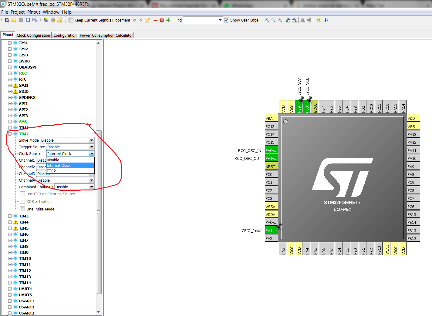
2.) Select the TIMx and choose clock source as internal clock.
3.) While setting up the clock, look at the APBx TIM clock. Also make sure this value is below 65000 to make the calculations more simpler.
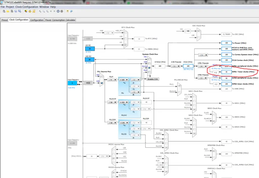
4.) Now my TIM2 is running at 45 MHz. So I will set my prescaler value at 45000 and I will get a frequency of 1 KHz (1 ms time period) from this setup. Also set the value of ARR to maximum possible value. As my ARR is 32 bit so I will set it to 0xffffffff.
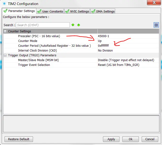
This setup will ensure that the Timer will count from 0 to 0xffffffff in 1 ms and it will increment the count by 1 in the CNT register.
Insight into the CODE
1
2
3
4
5
6
7
8
9
10
11
12
13
14
15
16
17
|
void read_freq (void)
{
htim2.Instance->CNT = 0; // set the count to 0
while ((htim2.Instance->CNT) < 1000) // while the count is less than 1000 ms
{
while (!(HAL_GPIO_ReadPin (GPIOA, GPIO_PIN_1))); // wait for the pin to go high
while ((HAL_GPIO_ReadPin (GPIOA, GPIO_PIN_1))); // wait for the pin to go low
increment++; // increment the variable
}
freq = increment; // freq = number of times pin goes high and low in second
increment = 0;
}
|

No comments:
Post a Comment