@par Example Description
This example describes how to customize the HAL time base using a general purpose timer instead of Systick as main source of time base.
In this example the used timer is TIM6.
Time base duration is kept unchanged: 1ms since PPP_TIMEOUT_VALUEs are defined and handled in milliseconds basis.
The example brings, in user file, a new implementation of the following HAL weak functions:
HAL_InitTick()
HAL_SuspendTick()
HAL_ResumeTick()
This implementation will overwrite native implementation in stm32f7xx_hal.c and so user functions will be invoked instead when called.
The following time base functions are kept as implemented natively:
HAL_IncTick()
HAL_Delay()
When user pushes the Tamper push-button, the Tick increment is suspended if it is already enabled, else it will be resumed.
In an infinite loop, LED1 toggles spaced out over 1s delay.
@note Care must be taken when using HAL_Delay(), this function provides accurate delay (in milliseconds)
based on variable incremented in TIM6 ISR. This implies that if HAL_Delay() is called from
a peripheral ISR process, then the TIM6 interrupt must have higher priority (numerically lower)
than the peripheral interrupt. Otherwise the caller ISR process will be blocked.
To change the TIM6 interrupt priority you have to use HAL_NVIC_SetPriority() function.
@note The application needs to ensure that the TIM6 time base is always set to 1 millisecond
to have correct HAL operation.
@par Keywords
System, General purpose Timer, Time base, HAL
@Note If the user code size exceeds the DTCM-RAM size or starts from internal cacheable memories (SRAM1 and SRAM2),that is shared between several processors,
then it is highly recommended to enable the CPU cache and maintain its coherence at application level.
The address and the size of cacheable buffers (shared between CPU and other masters) must be properly updated to be aligned to cache line size (32 bytes).
@Note It is recommended to enable the cache and maintain its coherence, but depending on the use case
It is also possible to configure the MPU as "Write through", to guarantee the write access coherence.
In that case, the MPU must be configured as Cacheable/Bufferable/Not Shareable.
Even though the user must manage the cache coherence for read accesses.
Please refer to the AN4838 “Managing memory protection unit (MPU) in STM32 MCUs”
Please refer to the AN4839 “Level 1 cache on STM32F7 Series”
uint32_t uwIncrementState = 0;
/* Private function prototypes -----------------------------------------------*/
static void SystemClock_Config(void);
static void CPU_CACHE_Enable(void);
/* Private functions ---------------------------------------------------------*/
/**
* @brief Main program
* @param None
* @retval None
*/
int main(void)
{
/* This sample code shows how to configure The HAL time base source base with a
dedicated Tick interrupt priority.
A general purpose timer (TIM6) is used instead of Systick as source of time base.
Time base duration is fixed to 1ms since PPP_TIMEOUT_VALUEs are defined and
handled in milliseconds basis.
*/
/* Enable the CPU Cache */
CPU_CACHE_Enable();
/* STM32F7xx HAL library initialization:
- Configure the Flash prefetch
- Configure timer (TIM6) to generate an interrupt each 1 msec
- Set NVIC Group Priority to 4
- Low Level Initialization
*/
HAL_Init();
/* Configure the system clock to 216 MHz */
SystemClock_Config();
/* Configure LED1 */
BSP_LED_Init(LED1);
/* Configure Tamper push-button */
BSP_PB_Init(BUTTON_KEY, BUTTON_MODE_EXTI);
/* Insert a Delay of 1000 ms and toggle LED2, in an infinite loop */
while (1)
{
/* Insert a 1s delay */
HAL_Delay(1000);
/* Toggle LED1 */
BSP_LED_Toggle(LED1);
}
}
/**
* @brief EXTI line detection callback.
* @param GPIO_Pin: Specifies the pins connected EXTI line
* @retval None
*/
void HAL_GPIO_EXTI_Callback(uint16_t GPIO_Pin)
{
if(GPIO_Pin == KEY_BUTTON_PIN)
{
if (uwIncrementState == 0)
{
/* Suspend tick increment */
HAL_SuspendTick();
/* Change the Push button state */
uwIncrementState = 1;
}
else
{
/* Resume tick increment */
HAL_ResumeTick();
/* Change the Push button state */
uwIncrementState = 0;
}
}
}
/**
* @brief System Clock Configuration
* The system Clock is configured as follow :
* System Clock source = PLL (HSE)
* SYSCLK(Hz) = 216000000
* HCLK(Hz) = 216000000
* AHB Prescaler = 1
* APB1 Prescaler = 4
* APB2 Prescaler = 2
* HSE Frequency(Hz) = 25000000
* PLL_M = 25
* PLL_N = 432
* PLL_P = 2
* PLL_Q = 9
* VDD(V) = 3.3
* Main regulator output voltage = Scale1 mode
* Flash Latency(WS) = 7
* @param None
* @retval None
*/
static void SystemClock_Config(void)
{
RCC_ClkInitTypeDef RCC_ClkInitStruct;
RCC_OscInitTypeDef RCC_OscInitStruct;
HAL_StatusTypeDef ret = HAL_OK;
/* Enable Power Control clock */
__HAL_RCC_PWR_CLK_ENABLE();
/* The voltage scaling allows optimizing the power consumption when the device is
clocked below the maximum system frequency, to update the voltage scaling value
regarding system frequency refer to product datasheet. */
__HAL_PWR_VOLTAGESCALING_CONFIG(PWR_REGULATOR_VOLTAGE_SCALE1);
/* Enable HSE Oscillator and activate PLL with HSE as source */
RCC_OscInitStruct.OscillatorType = RCC_OSCILLATORTYPE_HSE;
RCC_OscInitStruct.HSEState = RCC_HSE_ON;
RCC_OscInitStruct.PLL.PLLState = RCC_PLL_ON;
RCC_OscInitStruct.PLL.PLLSource = RCC_PLLSOURCE_HSE;
RCC_OscInitStruct.PLL.PLLM = 25;
RCC_OscInitStruct.PLL.PLLN = 432;
RCC_OscInitStruct.PLL.PLLP = RCC_PLLP_DIV2;
RCC_OscInitStruct.PLL.PLLQ = 9;
ret = HAL_RCC_OscConfig(&RCC_OscInitStruct);
if(ret != HAL_OK)
{
while(1) { ; }
}
/* Activate the OverDrive to reach the 216 MHz Frequency */
ret = HAL_PWREx_EnableOverDrive();
if(ret != HAL_OK)
{
while(1) { ; }
}
/* Select PLL as system clock source and configure the HCLK, PCLK1 and PCLK2 clocks dividers */
RCC_ClkInitStruct.ClockType = (RCC_CLOCKTYPE_SYSCLK | RCC_CLOCKTYPE_HCLK | RCC_CLOCKTYPE_PCLK1 | RCC_CLOCKTYPE_PCLK2);
RCC_ClkInitStruct.SYSCLKSource = RCC_SYSCLKSOURCE_PLLCLK;
RCC_ClkInitStruct.AHBCLKDivider = RCC_SYSCLK_DIV1;
RCC_ClkInitStruct.APB1CLKDivider = RCC_HCLK_DIV4;
RCC_ClkInitStruct.APB2CLKDivider = RCC_HCLK_DIV2;
ret = HAL_RCC_ClockConfig(&RCC_ClkInitStruct, FLASH_LATENCY_7);
if(ret != HAL_OK)
{
while(1) { ; }
}
}
/**
* @brief CPU L1-Cache enable.
* @param None
* @retval None
*/
static void CPU_CACHE_Enable(void)
{
/* Enable I-Cache */
SCB_EnableICache();
/* Enable D-Cache */
SCB_EnableDCache();
}
Showing posts with label arm stm32. Show all posts
Showing posts with label arm stm32. Show all posts
Tuesday, April 14, 2020

Tuesday, June 11, 2019
LED dot matrix and STM32
We all come across some kind of DOT matrix displays in our daily lives. Those sign boards scrolling from one end to another end and some of them even displaying some cool animation. Today in this tutorial I will show you guys How to interface LED dot matrix with STM32.
We are only going to cover the initial part today i.e. display some characters on a single 8×8 dot matrix and scrolling and other features will be covered in upcoming tutorial.
HOW TO
First let’s see how the display even works. I have a 8×8 led display attached to a MAX7219 driver IC. The MAX7219 is compact, serial input/output common-cathode display drivers that interface microprocessors to 7- segment numeric LED displays of up to 8 digits, bar-graph displays, or 64 individual LEDs.
The following are the features of MAX7219
The following are the features of MAX7219
- Individual LED Segment Control
- Decode/No-Decode Digit Selection
- 150µA Low-Power Shutdown (Data Retained)
- Digital and Analog Brightness Control
- Display Blanked on Power-Up
- Drive Common-Cathode LED Display
- Slew-Rate Limited Segment Drivers for Lower EMI (MAX7221)
- SPI, QSPI, MICROWIRE Serial Interface (MAX7221)
- 24-Pin DIP and SO Packages
On going through the datasheet of MAX7219, you will notice the timing diagram and the data format diagram on page-6.
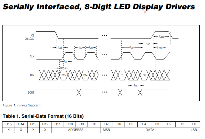
According to the above diagram, In order to write data to max7219, we need to do the following:-
1.) Pull the CS pin LOW
2.) Pull the clock pin LOW
3.) Write one bit to the data pin
4.) Pull the clock pin HIGH
5.) Repeat steps 2,3 and 4 until both address and data bytes are written
6.) Pull the CS pin HIGH
1.) Pull the CS pin LOW
2.) Pull the clock pin LOW
3.) Write one bit to the data pin
4.) Pull the clock pin HIGH
5.) Repeat steps 2,3 and 4 until both address and data bytes are written
6.) Pull the CS pin HIGH
Also note that the data should be written in MSB first format. Let’s write the code for STM32 now. My CubeMx configuration is shown below..
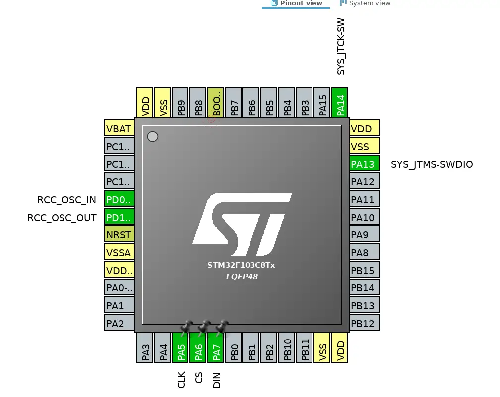
Some Insight into the CODE
The following is the function for writing a byte to max7219
As you can see above that for writing each bit of data, we have to Pull the CLK pin low and than pull it high after writing the bit. Also byte&0x80 means that we are writing the MSB bit and than shifting the bit to left by using byte<<1.
Next we need to write another function for writing address and data to the MAX.
Next we need to write another function for writing address and data to the MAX.
Here we have to pull the CS pin LOW and after writing both address and data, pull it back to HIGH.

TO initialise the DOT matrix display we have to do the following:-
–> Set noo decode in the Decode mode register (0x09)
–> Set intensity value in the intensity register (0x0A)
–> Scan limit = 8 LEDs in 0x0b
–> value of 1 in the 0x0c denotes the normal power on mode
–> Set 0 in the Display test register (0x0f)
–> Set noo decode in the Decode mode register (0x09)
–> Set intensity value in the intensity register (0x0A)
–> Scan limit = 8 LEDs in 0x0b
–> value of 1 in the 0x0c denotes the normal power on mode
–> Set 0 in the Display test register (0x0f)
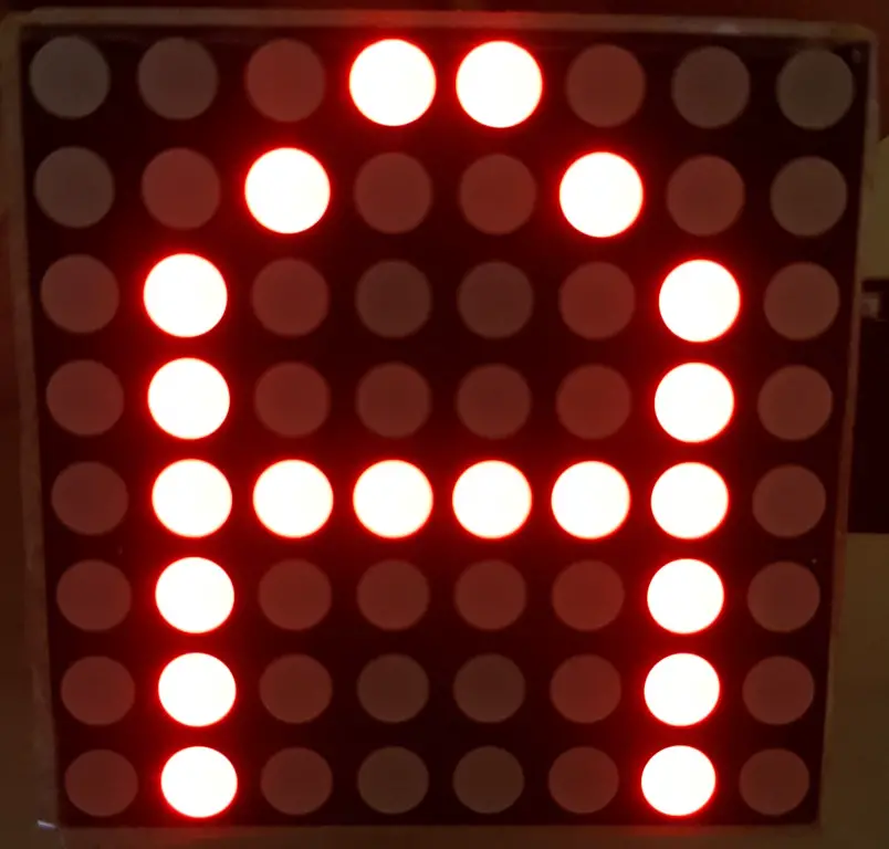
Now in order to display any character (For eg ‘A’), Think of the Registers from 0x01 to 0x08 as the addresses of the 8 ROWs and we need to turn the respective LEDs ON in each ROW. The following are the values for each row to display ‘A’
{0x18,0x24,0x42,0x42,0x7E,0x42,0x42,0x42}
You can check the code for more details.
{0x18,0x24,0x42,0x42,0x7E,0x42,0x42,0x42}
You can check the code for more details.
How to create 1 microsecond delay in STM32
HAL_Delay is able to provide minimum 1ms delay but when it comes to microsecond, there isn’t any predefined function to create 1us delay. In this tutorial, I am going to show you how to create 1 microsecond delay in STM32. The process will be same for all the STM32 devices, you need to make a minor change though.
WHY Delay in MicroSeconds
Delay in microseconds is needed in order to interface some sensors for eg- DHT11/22. These sensors contains only one PIN for the data transfer and data is transferred bidirectionally. They need precise timing in order to work. For eg- To initialize DHT22, microcontroller need to pull the data pin low for 500us and than pull high for 40us. After that DHT22 start transmitting it’s response by pulling the line low for 80us followed by pulling high for 80us.
After searching a lot on the internet, finally I got the code which works. I don’t remember where I got it from so if someone knows the writer, do let me know in the comments below. I will give the credits for the work.
I will show the working on the oscilloscope, You can check the RESULTS tab for more details. I am using STM32F103C8 cortex M3 microcontroller but the process is same for other STM32 devices.
How to setup
This project contains a header file (dwt_stm32_delay.h) and a c file (dwt_stm32_delay.c). We need to include it in the main project. I am using keil and the process is described below:
First setup the project from the CubeMx and right click the Application/Userand select add existing files to group

add both files in the project

As you can see above that the folder is included in the path
Next you have to include dwt_stm32_delay.h in the main file by using #include “dwt_stm32_delay.h” and build the project. Now you will be able to see the *.h and *.c file in the list.
NOTE:- Inside dwt_stm32_delay.h, change the #include”*.h” file according to your microcontroller.
You can use DWT_Delay_Init (); to initialize the delay and DWT_Delay_us (microseconds) for the delay in us.
//dwt_delay/dwt_delay.h
| #include <stdint.h> | |
| #ifndef INC_DWT_DELAY_H_ | |
| #define INC_DWT_DELAY_H_ | |
| #define DWT_DELAY_NEWBIE 0 | |
| void DWT_Init(void); | |
| void DWT_Delay(uint32_t us); | |
| #endif /* INC_DWT_DELAY_DWT_DELAY_H_ */ |
//dwt_delay/dwt_delay.c
#include "stm32f1xx_hal.h" // change to whatever MCU you use
#include "dwt_delay.h"
/**
* Initialization routine.
* You might need to enable access to DWT registers on Cortex-M7
* DWT->LAR = 0xC5ACCE55
*/
void DWT_Init(void)
{
if (!(CoreDebug->DEMCR & CoreDebug_DEMCR_TRCENA_Msk)) {
CoreDebug->DEMCR |= CoreDebug_DEMCR_TRCENA_Msk;
DWT->CYCCNT = 0;
DWT->CTRL |= DWT_CTRL_CYCCNTENA_Msk;
}
}
#if DWT_DELAY_NEWBIE
/**
* If you are a newbie and see magic in DWT_Delay, consider this more
* illustrative function, where you explicitly determine a counter
* value when delay should stop while keeping things in bounds of uint32.
*/
void DWT_Delay(uint32_t us) // microseconds
{
uint32_t startTick = DWT->CYCCNT,
targetTick = DWT->CYCCNT + us * (SystemCoreClock/1000000);
// Must check if target tick is out of bounds and overflowed
if (targetTick > startTick) {
// Not overflowed
while (DWT->CYCCNT < targetTick);
} else {
// Overflowed
while (DWT->CYCCNT > startTick || DWT->CYCCNT < targetTick);
}
}
#else
/**
* Delay routine itself.
* Time is in microseconds (1/1000000th of a second), not to be
* confused with millisecond (1/1000th).
*
* No need to check an overflow. Let it just tick :)
*
* @param uint32_t us Number of microseconds to delay for
*/
void DWT_Delay(uint32_t us) // microseconds
{
uint32_t startTick = DWT->CYCCNT,
delayTicks = us * (SystemCoreClock/1000000);
while (DWT->CYCCNT - startTick < delayTicks);
}
#endif
Subscribe to:
Posts (Atom)
