Showing posts with label avr. Show all posts

Friday, September 13, 2019

SPI Transfer Modes

SPI interface allows to transmit and receive data simultaneously on two lines (MOSI and MISO). Clock polarity (CPOL) and clock phase (CPHA) are the main parameters that define a clock format to be used by the SPI bus. Depending on CPOL parameter, SPI clock may be inverted or non-inverted. CPHA parameter is used to shift the sampling phase. If CPHA=0 the data are sampled on the leading (first) clock edge. If CPHA=1 the data are sampled on the trailing (second) clock edge, regardless of whether that clock edge is rising or falling.

CPOL=0, CPHA=0

spi-cpol-0-cpha-0.png
The data must be available before the first clock signal rising. The clock idle state is zero. The data on MISO and MOSI lines must be stable while the clock is high and can be changed when the clock is low. The data is captured on the clock's low-to-high transition and propagated on high-to-low clock transition.

CPOL=0, CPHA=1

spi-cpol-0-cpha-1.png
The first clock signal rising can be used to prepare the data. The clock idle state is zero. The data on MISO and MOSI lines must be stable while the clock is low and can be changed when the clock is high. The data is captured on the clock's high-to-low transition and propagated on low-to-high clock transition.

CPOL=1, CPHA=0

spi-cpol-1-cpha-0.png
The data must be available before the first clock signal falling. The clock idle state is one. The data on MISO and MOSI lines must be stable while the clock is low and can be changed when the clock is high. The data is captured on the clock's high-to-low transition and propagated on low-to-high clock transition.

CPOL=1, CPHA=1

spi-cpol-1-cpha-1.png
The first clock signal falling can be used to prepare the data. The clock idle state is one. The data on MISO and MOSI lines must be stable while the clock is high and can be changed when the clock is low. The data is captured on the clock's low-to-high transition and propagated on high-to-low clock transition.

Thursday, June 20, 2019

Fix Error file dep/main.o.d: No such file or directory --- when Compile AVR Studio using Win AVR - GCC on win 8.1,Win 10

Error:
0 [main] sh 2312 sync_with_child: child 4744(0x14C) died before initialization with status code 0xC0000142
73796 [main] sh 2312 sync_with_child: *** child state waiting for longjmp
/usr/bin/sh: fork: Resource temporarily unavailable
rm -rf main.o test.elf dep/* test.hex test.eep test.lss test.map
make: [clean] Error -1073741502 (ignored)
Build succeeded with 0 Warnings...
0 [main] sh 1484 sync_with_child: child 2300(0x14C) died before initialization with status code 0xC0000142
64185 [main] sh 1484 sync_with_child: *** child state waiting for longjmp
/usr/bin/sh: fork: Resource temporarily unavailable
avr-gcc -mmcu=atmega644pa -Wall -gdwarf-2 -std=gnu99 -DF_CPU=3686400UL -Os -funsigned-char -funsigned-bitfields -fpack-struct -fshort-enums -MD -MP -MT main.o -MF dep/main.o.d -c ../main.c
../main.c:57: fatal error: opening dependency file dep/main.o.d: No such file or directory
compilation terminated.
make: *** [main.o] Error 1
Build failed with 1 errors and 0 warnings...


=> Solution:
Download this file and put it to folder install Win AVR (GCC) : utils\bin directory (WinAVR)
Link:http://www.madwizard.org/download/electronics/msys-1.0-vista64.zip

Thursday, June 13, 2019

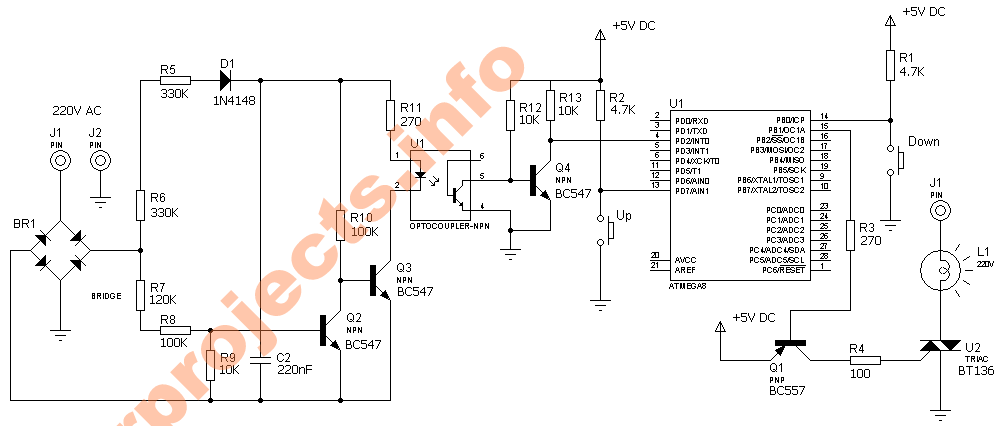
Digital dimmer using Microcontroller atmega8

This project is used to control the brightness of the lamp or can be used to control the speed of the fan.
The system consists of 3 block they are.


  1. Zero crossing detector
  2. Microcontroller (Atmega8)
  3. Load Driver (BT136)Digital dimmerAs the name implies the zero crossing detector generates pulses for every zero crossing of the input AC signal. This pulses are fed to the microcontroller interrupt pin through the opto coupler. The opto coupler is used for the isolation of the high voltage AC to the low voltage DC supply at the microcontroller side.
  4. The microcontroller was interrupted for every zero crossing which switch on the TRIACas per the user need. The user can increase or decrease the output voltage with help of 2 push buttons.The TRIAC BT136 is used to drive the load. It can withstand a maximum load of 5A. You can also use an opto coupler at the TRIACfiring side.


PWM DC motor control using MOSFET H-Bridge with AVR ATmega8

Hi friends,
here is a very simple project of controlling a small DC-motor (taken from an old personal cassette player) with ATmega8. The ATmega8 is having three PWM channels, out of which two are used here. PWM waveforms are fed to MOSFET (RFD3055) H-bridge.
Here, direction is controlled using a two-position toggle switch and speed of the motor is controlled by two push-buttons, one for increasing the speed and other for reducing.
The schematic is geiven here (click on the image to enlarge):


When switch SW1 is closed, OC1A channel is active which will feed the PWM signal to Q1 & Q4 MOSFETs. The OC1B pin will remain low keeping the Q3 & Q2 in OFF condition. When SW1 is toggled to open position, OC1A pin will become low, making Q1 & Q4 OFF and OC1B will feed the PWM signal to Q3 & Q2, resulting in the change in the direction of current flow hrough motor. Hence, motor rotation direction will change.
The speed is controlled by Push-buttons S2 & S3. Pressing S2 will increase the speed in fixed steps. Similarly, pressing S3 will reduce the speed in fixed steps.

The closer look to the motor and the circuit:


Interfacing RTC Ds1307 & serial EEPROM using i2c bus, with ATmega128


Hi friends,
here is my experiment with i2c bus for interfacing serial EEPROM (24C256) and RTC (DS1307) using AVR microcontroller ATmega128. The circuit is also provided with an RS232 port for connecting with PC to send commands for reading/writing EEPROM or setting date/time in RTC (Click on images to enlarge them).

Communication with PC is done through Hyper Terminal. A screen shot of the message sent to PC by microcontroller immediately after power ON is shown in the figure at the left, where the user is asked to enter choice from the menu options related to EEPROM and RTC. User can store data in EEPROM, or set RTC date and time by entering them using PC keyboard.
Hyper Terminal is used with 19200 Baud, No parity, No hardware flow control settings.

When the circuit is powered on, a welcome message is displayed on the Hyper Terminal window and a menu with 9 options (0-8) is displayed (refer to the figure). The options are explained here:

0: Erase EEPROM (fills eeprom with 0xff bytes)
1: Write EEPROM (starts writing eeprom starting with 0x0000 address)
2: Read EEPROM (reads eeprom starting with 0x0000 address)
3: Write eeprom page (writes one page of eeprom at specified page number)
4: Read eeprom page (Reads one page of eeprom at specified page number)
5: Display RTC Date (Displays current date from RTC)
6: Display RTC time (Displays current time from RTC)
7: Update RTC Date (Setting new date in RTC)
8: Update RTC time (Setting new time in RTC)

The option is selected from PC keyboard. While writing to eeprom or RTC the data is entered using PC keyboard as specified by the program.

The software routines include DS1307 library, 24C256 library & I2C library along with the main function.

The code is written in C using winAVR (inside AVRStudio). The complete project folder can be downloaded here in zip format (updated on 25-April-2009, earlier it was in ICCAVR format):

Here is running simulation on Proteus ISIS (click on image to enlarge it):


Source code: https://www.dharmanitech.com/search/label/Thermometer

NOKIA 3310 LCD interfacing with AVR - ATmega8

Hi friends,
using graphic LCD in a project gives itreally a good look and flexibility of displaying different characters and shapes. But, the graphic LCDs are quite costly.
The NOKIA 3310 LCD provides a really low-cost solution to add a small graphic display into your project and also good for learning purpose. The LCD is SPI bus compatible, saving many pins for other uses. It operates at 3.3v.

Here is a small circuit for interfacing the 3310 LCD with AVR microcontroller ATmega8. The schematic includes LCD connection with SPI port of ATmega8 with other connections required by LCD. The 3.3v is generated using adjustable voltage regulator LM317 (I was not having any 3.3v regulator at the moment). An LED is also connected with microcontroller just for making sure that the controller is working, particularly when you don't see anything on the display!

Here is the schematic and the pin details of the LCD:
[schematic.JPG]


The connector of LCD is 'touch' type. So, I made a small connecor PCB with tracks touching to the pins of LCD. The pcb was pasted at backside of LCD using cello tapes as shown in the back-view image
.


Here is a testing with Proteus ISIS Simulation:

The program routines are written in C with ICCAVR compiler. I've created a library for this display. The low-cost, easy availability has made me relly like this display.
I'm going to use it for
doing other stuffs, too!

Back to Top