Showing posts with label dac stm32. Show all posts

Thursday, April 9, 2020

$3- DAC_SignalsGeneration | STM32F7 Tutorial | Example code with HAL

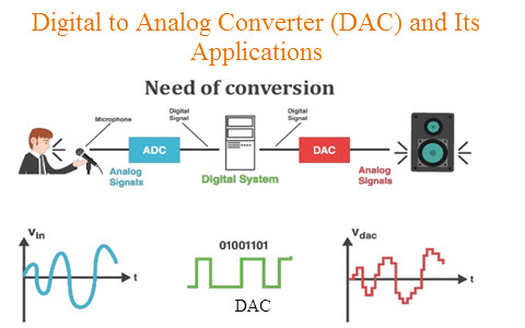
DIgital to Analog Converter (DAC) Architecture and its Applications


@par Example Description

How to use the DAC peripheral to generate several signals using the DMA controller.

For each press on User push-button, a signal has been selected and can be monitored on 
the DAC channel one:
    - Triangle waveform (Channel 1).
    - Escalator waveform (Channel 1) using DMA transfer.


STM32746G-DISCOVERY board's LED can be used to monitor the process status:
  - LED1 is slowly blinking (1 sec. period) and example is stopped (using infinite loop)
  when there is an error during process.

@note Care must be taken when using HAL_Delay(), this function provides accurate delay (in milliseconds)
      based on variable incremented in SysTick ISR. This implies that if HAL_Delay() is called from
      a peripheral ISR process, then the SysTick interrupt must have higher priority (numerically lower)
      than the peripheral interrupt. Otherwise the caller ISR process will be blocked.
      To change the SysTick interrupt priority you have to use HAL_NVIC_SetPriority() function.
     
@note The application need to ensure that the SysTick time base is always set to 1 millisecond
      to have correct HAL operation.
   
@par Keywords

Analog, DAC, Signals generation, DMA, Triangle, Escalator, Waveform, Amplitude
 
@Note If the user code size exceeds the DTCM-RAM size or starts from internal cacheable memories (SRAM1 and SRAM2),that is shared between several processors,
      then it is highly recommended to enable the CPU cache and maintain its coherence at application level.
      The address and the size of cacheable buffers (shared between CPU and other masters)  must be properly updated to be aligned to cache line size (32 bytes).

@Note It is recommended to enable the cache and maintain its coherence, but depending on the use case
      It is also possible to configure the MPU as "Write through", to guarantee the write access coherence.
      In that case, the MPU must be configured as Cacheable/Bufferable/Not Shareable.
      Even though the user must manage the cache coherence for read accesses.
      Please refer to the AN4838 “Managing memory protection unit (MPU) in STM32 MCUs”
      Please refer to the AN4839 “Level 1 cache on STM32F7 Series”


1. main.h
/* Define to prevent recursive inclusion -------------------------------------*/
#ifndef __MAIN_H
#define __MAIN_H

/* Includes ------------------------------------------------------------------*/
#include "stm32f7xx_hal.h"
#include "stm32746g_discovery.h"


/* Exported types ------------------------------------------------------------*/
/* Exported constants --------------------------------------------------------*/
/* User can use this section to tailor DACx instance used and associated resources */
/* Definition for DACx clock resources */
#define DACx                            DAC
#define DACx_CHANNEL_GPIO_CLK_ENABLE()  __HAL_RCC_GPIOA_CLK_ENABLE()
#define DMAx_CLK_ENABLE()               __HAL_RCC_DMA1_CLK_ENABLE()

#define DACx_CLK_ENABLE()               __HAL_RCC_DAC_CLK_ENABLE()
#define DACx_FORCE_RESET()              __HAL_RCC_DAC_FORCE_RESET()
#define DACx_RELEASE_RESET()            __HAL_RCC_DAC_RELEASE_RESET()

/* Definition for DACx Channel Pin */
#define DACx_CHANNEL_PIN                GPIO_PIN_4
#define DACx_CHANNEL_GPIO_PORT          GPIOA

/* Definition for DACx's Channel */
#define DACx_DMA_CHANNEL                DMA_CHANNEL_7

#define DACx_CHANNEL                    DAC_CHANNEL_1

/* Definition for DACx's DMA_STREAM */
#define DACx_DMA_INSTANCE               DMA1_Stream5

/* Definition for DACx's NVIC */
#define DACx_DMA_IRQn                   DMA1_Stream5_IRQn
#define DACx_DMA_IRQHandler             DMA1_Stream5_IRQHandler

/* Exported macro ------------------------------------------------------------*/
/* Exported functions ------------------------------------------------------- */

#endif /* __MAIN_H */


2.main.c

DAC_HandleTypeDef    DacHandle;
static DAC_ChannelConfTypeDef sConfig;
const uint8_t aEscalator8bit[6] = {0x0, 0x33, 0x66, 0x99, 0xCC, 0xFF};
__IO uint8_t ubSelectedWavesForm = 1;
__IO uint8_t ubKeyPressed = SET;

/* Private function prototypes -----------------------------------------------*/
static void DAC_Ch1_TriangleConfig(void);
static void DAC_Ch1_EscalatorConfig(void);
static void TIM6_Config(void);
void SystemClock_Config(void);
static void Error_Handler(void);
static void CPU_CACHE_Enable(void);

/* Private functions ---------------------------------------------------------*/

/**
  * @brief  Main program.
  * @param  None
  * @retval None
  */
int main(void)
{
  /* Enable the CPU Cache */
  CPU_CACHE_Enable();

  /* STM32F7xx HAL library initialization:
       - Configure the Flash prefetch
       - Systick timer is configured by default as source of time base, but user
         can eventually implement his proper time base source (a general purpose
         timer for example or other time source), keeping in mind that Time base
         duration should be kept 1ms since PPP_TIMEOUT_VALUEs are defined and
         handled in milliseconds basis.
       - Set NVIC Group Priority to 4
       - Low Level Initialization
     */
  HAL_Init();

  /* Configure the system clock to 216 MHz */
  SystemClock_Config();
 
   /* Configure LED1 */
  BSP_LED_Init(LED1);

  /* Configures User push-button */
  BSP_PB_Init(BUTTON_KEY, BUTTON_MODE_EXTI);
 
  /*##-1- Configure the DAC peripheral #######################################*/
  DacHandle.Instance = DACx;

  /*##-2- Configure the TIM peripheral #######################################*/
  TIM6_Config();

  /* Infinite loop */
  while (1)
  {
    /* If the Key is pressed */
    if (ubKeyPressed != RESET)
    {
      HAL_DAC_DeInit(&DacHandle);

      /* select waves forms according to the User push-button status */
      if (ubSelectedWavesForm == 1)
      {
        /* The triangle wave has been selected */

        /* Triangle Wave generator -------------------------------------------*/
        DAC_Ch1_TriangleConfig();
      }
      else
      {
        /* The escalator wave has been selected */

        /* Escalator Wave generator -------------------------------------------*/
        DAC_Ch1_EscalatorConfig();
      }

      ubKeyPressed = RESET;
    }
  }
}

/**
  * @brief  System Clock Configuration
  *         The system Clock is configured as follow :
  *            System Clock source            = PLL (HSE)
  *            SYSCLK(Hz)                     = 216000000
  *            HCLK(Hz)                       = 216000000
  *            AHB Prescaler                  = 1
  *            APB1 Prescaler                 = 4
  *            APB2 Prescaler                 = 2
  *            HSE Frequency(Hz)              = 25000000
  *            PLL_M                          = 25
  *            PLL_N                          = 432
  *            PLL_P                          = 2
  *            PLL_Q                          = 9
  *            VDD(V)                         = 3.3
  *            Main regulator output voltage  = Scale1 mode
  *            Flash Latency(WS)              = 7
  * @param  None
  * @retval None
  */
void SystemClock_Config(void)
{
  RCC_ClkInitTypeDef RCC_ClkInitStruct;
  RCC_OscInitTypeDef RCC_OscInitStruct;
  HAL_StatusTypeDef ret = HAL_OK;

  /* Enable HSE Oscillator and activate PLL with HSE as source */
  RCC_OscInitStruct.OscillatorType = RCC_OSCILLATORTYPE_HSE;
  RCC_OscInitStruct.HSEState = RCC_HSE_ON;
  RCC_OscInitStruct.PLL.PLLState = RCC_PLL_ON;
  RCC_OscInitStruct.PLL.PLLSource = RCC_PLLSOURCE_HSE;
  RCC_OscInitStruct.PLL.PLLM = 25;
  RCC_OscInitStruct.PLL.PLLN = 432;
  RCC_OscInitStruct.PLL.PLLP = RCC_PLLP_DIV2;
  RCC_OscInitStruct.PLL.PLLQ = 9;
 
  ret = HAL_RCC_OscConfig(&RCC_OscInitStruct);
  if(ret != HAL_OK)
  {
    while(1) { ; }
  }
 
  /* Activate the OverDrive to reach the 216 MHz Frequency */ 
  ret = HAL_PWREx_EnableOverDrive();
  if(ret != HAL_OK)
  {
    while(1) { ; }
  }
 
  /* Select PLL as system clock source and configure the HCLK, PCLK1 and PCLK2 clocks dividers */
  RCC_ClkInitStruct.ClockType = (RCC_CLOCKTYPE_SYSCLK | RCC_CLOCKTYPE_HCLK | RCC_CLOCKTYPE_PCLK1 | RCC_CLOCKTYPE_PCLK2);
  RCC_ClkInitStruct.SYSCLKSource = RCC_SYSCLKSOURCE_PLLCLK;
  RCC_ClkInitStruct.AHBCLKDivider = RCC_SYSCLK_DIV1;
  RCC_ClkInitStruct.APB1CLKDivider = RCC_HCLK_DIV4; 
  RCC_ClkInitStruct.APB2CLKDivider = RCC_HCLK_DIV2;
 
  ret = HAL_RCC_ClockConfig(&RCC_ClkInitStruct, FLASH_LATENCY_7);
  if(ret != HAL_OK)
  {
    while(1) { ; }
  } 
}

/**
  * @brief  This function is executed in case of error occurrence.
  * @param  None
  * @retval None
  */
static void Error_Handler(void)
{
  /* Error if LED1 is slowly blinking (1 sec. period) */
  while(1)
  {   
    BSP_LED_Toggle(LED1);
    HAL_Delay(1000);
  }
}

static void DAC_Ch1_EscalatorConfig(void)
{
  /*##-1- Initialize the DAC peripheral ######################################*/
  if (HAL_DAC_Init(&DacHandle) != HAL_OK)
  {
    /* Initialization Error */
    Error_Handler();
  }

  /*##-1- DAC channel1 Configuration #########################################*/
  sConfig.DAC_Trigger = DAC_TRIGGER_T6_TRGO;
  sConfig.DAC_OutputBuffer = DAC_OUTPUTBUFFER_ENABLE;

  if (HAL_DAC_ConfigChannel(&DacHandle, &sConfig, DACx_CHANNEL) != HAL_OK)
  {
    /* Channel configuration Error */
    Error_Handler();
  }

  /*##-2- Enable DAC selected channel and associated DMA #############################*/
  if (HAL_DAC_Start_DMA(&DacHandle, DACx_CHANNEL, (uint32_t *)aEscalator8bit, 6, DAC_ALIGN_8B_R) != HAL_OK)
  {
    /* Start DMA Error */
    Error_Handler();
  }
}

/**
  * @brief  DAC Channel1 Triangle Configuration
  * @param  None
  * @retval None
  */
static void DAC_Ch1_TriangleConfig(void)
{
  /*##-1- Initialize the DAC peripheral ######################################*/
  if (HAL_DAC_Init(&DacHandle) != HAL_OK)
  {
    /* DAC initialization Error */
    Error_Handler();
  }

  /*##-2- DAC channel2 Configuration #########################################*/
  sConfig.DAC_Trigger = DAC_TRIGGER_T6_TRGO;
  sConfig.DAC_OutputBuffer = DAC_OUTPUTBUFFER_ENABLE;

  if (HAL_DAC_ConfigChannel(&DacHandle, &sConfig, DACx_CHANNEL) != HAL_OK)
  {
    /* Channel configuration Error */
    Error_Handler();
  }

  /*##-3- DAC channel2 Triangle Wave generation configuration ################*/
  if (HAL_DACEx_TriangleWaveGenerate(&DacHandle, DACx_CHANNEL, DAC_TRIANGLEAMPLITUDE_1023) != HAL_OK)
  {
    /* Triangle wave generation Error */
    Error_Handler();
  }

  /*##-4- Enable DAC Channel1 ################################################*/
  if (HAL_DAC_Start(&DacHandle, DACx_CHANNEL) != HAL_OK)
  {
    /* Start Error */
    Error_Handler();
  }

  /*##-5- Set DAC channel1 DHR12RD register ################################################*/
  if (HAL_DAC_SetValue(&DacHandle, DACx_CHANNEL, DAC_ALIGN_12B_R, 0x100) != HAL_OK)
  {
    /* Setting value Error */
    Error_Handler();
  }
}

/**
  * @brief EXTI line detection callbacks
  * @param GPIO_Pin: Specifies the pins connected EXTI line
  * @retval None
  */
void HAL_GPIO_EXTI_Callback(uint16_t GPIO_Pin)
{
  /* Change the wave */
  ubKeyPressed = 1;

  /* Change the selected waves forms */
  ubSelectedWavesForm = !ubSelectedWavesForm;
}

/**
  * @brief  TIM6 Configuration
  * @note   TIM6 configuration is based on APB1 frequency
  * @note   TIM6 Update event occurs each TIM6CLK/256
  * @param  None
  * @retval None
  */
void TIM6_Config(void)
{
  static TIM_HandleTypeDef  htim;
  TIM_MasterConfigTypeDef sMasterConfig;

  /*##-1- Configure the TIM peripheral #######################################*/
  /* Time base configuration */
  htim.Instance = TIM6;

  htim.Init.Period            = 0x7FF;
  htim.Init.Prescaler         = 0;
  htim.Init.ClockDivision     = 0;
  htim.Init.CounterMode       = TIM_COUNTERMODE_UP;
  htim.Init.RepetitionCounter = 0;
  htim.Init.AutoReloadPreload = TIM_AUTORELOAD_PRELOAD_DISABLE;
  HAL_TIM_Base_Init(&htim);

  /* TIM6 TRGO selection */
  sMasterConfig.MasterOutputTrigger = TIM_TRGO_UPDATE;
  sMasterConfig.MasterSlaveMode = TIM_MASTERSLAVEMODE_DISABLE;

  HAL_TIMEx_MasterConfigSynchronization(&htim, &sMasterConfig);

  /*##-2- Enable TIM peripheral counter ######################################*/
  HAL_TIM_Base_Start(&htim);
}

/**
  * @brief  CPU L1-Cache enable.
  * @param  None
  * @retval None
  */
static void CPU_CACHE_Enable(void)
{
  /* Enable I-Cache */
  SCB_EnableICache();

  /* Enable D-Cache */
  SCB_EnableDCache();
}

Thursday, April 2, 2020

DAC with STM32 | Example code STM32 with Standard Peripheral Lib

@par Example Description 

This example provides a short description of how to use the DAC peripheral to
generate several signals using DMA controller.
When the user presses the KEY push-button, DMA transfers the two selected
waveforms to the DAC.
For each press on KEY button, 2 signals has been selected and can be monitored on
the two DAC channels:
    - Escalator waveform (Channel 1) and Sine waveForm (Channel 2).
    - Noise waveform (Channel 1) and Triangle waveform (Channel 2).


@par Directory contents 

  - DAC/DAC_SignalsGeneration/stm32f4xx_conf.h    Library Configuration file
  - DAC/DAC_SignalsGeneration/stm32f4xx_it.c      Interrupt handlers
  - DAC/DAC_SignalsGeneration/stm32f4xx_it.h      Interrupt handlers header file
  - DAC/DAC_SignalsGeneration/main.c              Main program
  - DAC/DAC_SignalsGeneration/main.h              Main program header file
  - DAC/DAC_SignalsGeneration/system_stm32f4xx.c  STM32F4xx system source file

1.main.h
/* Define to prevent recursive inclusion -------------------------------------*/
#ifndef __MAIN_H
#define __MAIN_H

/* Includes ------------------------------------------------------------------*/
#include "stm32f4xx.h"

#if defined (USE_STM324xG_EVAL)
  #include "stm324xg_eval.h"

#elif defined (USE_STM324x7I_EVAL)
  #include "stm324x7i_eval.h"

#else
 #error "Please select first the Evaluation board used in your application (in Project Options)"
#endif

/* Exported types ------------------------------------------------------------*/
/* Exported constants --------------------------------------------------------*/
/* Exported macro ------------------------------------------------------------*/
#if defined (USE_STM324xG_EVAL)

  #define DAC_DHR12R2_ADDRESS    0x40007414
  #define DAC_DHR8R1_ADDRESS     0x40007410

#else /* defined (USE_STM324x7I_EVAL)*/

  #define DAC_DHR12R2_ADDRESS    0x40007414
  #define DAC_DHR8R1_ADDRESS     0x40007410

#endif
/* Exported functions ------------------------------------------------------- */

#endif /* __MAIN_H */


2.main.c
/* Includes ------------------------------------------------------------------*/
#include "main.h"

/** @addtogroup STM32F4xx_StdPeriph_Examples
  * @{
  */

/** @addtogroup DAC_SignalsGeneration
  * @{
  */

/* Private typedef -----------------------------------------------------------*/
/* Private define ------------------------------------------------------------*/
/* Private macro -------------------------------------------------------------*/
/* Private variables ---------------------------------------------------------*/
DAC_InitTypeDef  DAC_InitStructure;

const uint16_t aSine12bit[32] = {
                      2047, 2447, 2831, 3185, 3498, 3750, 3939, 4056, 4095, 4056,
                      3939, 3750, 3495, 3185, 2831, 2447, 2047, 1647, 1263, 909,
                      599, 344, 155, 38, 0, 38, 155, 344, 599, 909, 1263, 1647};
const uint8_t aEscalator8bit[6] = {0x0, 0x33, 0x66, 0x99, 0xCC, 0xFF};

__IO uint8_t ubSelectedWavesForm = 1;
__IO uint8_t ubKeyPressed = SET;

/* Private function prototypes -----------------------------------------------*/
static void TIM6_Config(void);

static void DAC_Ch1_EscalatorConfig(void);
static void DAC_Ch2_SineWaveConfig(void);

static void DAC_Ch1_NoiseConfig(void);
static void DAC_Ch2_TriangleConfig(void);

/* Private functions ---------------------------------------------------------*/

/**
  * @brief   Main program
  * @param  None
  * @retval None
  */
int main(void)
{
  /*!< At this stage the microcontroller clock setting is already configured,
       this is done through SystemInit() function which is called from startup
       files (startup_stm32f40xx.s/startup_stm32f427x.s) before to branch to
       application main.
       To reconfigure the default setting of SystemInit() function, refer to
       system_stm32f4xx.c file
     */   

  /* Preconfiguration before using DAC----------------------------------------*/
  GPIO_InitTypeDef GPIO_InitStructure;

  /* DMA1 clock enable */
  RCC_AHB1PeriphClockCmd(RCC_AHB1Periph_DMA1, ENABLE);
  /* GPIOA clock enable (to be used with DAC) */
  RCC_AHB1PeriphClockCmd(RCC_AHB1Periph_GPIOA, ENABLE);                       
  /* DAC Periph clock enable */
  RCC_APB1PeriphClockCmd(RCC_APB1Periph_DAC, ENABLE);

  /* DAC channel 1 & 2 (DAC_OUT1 = PA.4)(DAC_OUT2 = PA.5) configuration */
  GPIO_InitStructure.GPIO_Pin = GPIO_Pin_4 | GPIO_Pin_5;
  GPIO_InitStructure.GPIO_Mode = GPIO_Mode_AN;
  GPIO_InitStructure.GPIO_PuPd = GPIO_PuPd_NOPULL;
  GPIO_Init(GPIOA, &GPIO_InitStructure);

  /* TIM6 Configuration ------------------------------------------------------*/
  TIM6_Config(); 
 
  /* Configures Key Button */
  STM_EVAL_PBInit(BUTTON_KEY, BUTTON_MODE_EXTI);
 
  while (1)
  {
    /* If the Key is pressed */
    if (ubKeyPressed != RESET)
    {           
      DAC_DeInit();

      /* select waves forms according to the Key Button status */
      if (ubSelectedWavesForm == 1)
      {
        /* The sine wave and the escalator wave has been selected */

        /* Escalator Wave generator ------------------------------------------*/
        DAC_Ch1_EscalatorConfig();

        /* Sine Wave generator -----------------------------------------------*/
        DAC_Ch2_SineWaveConfig();
       
      }
      else
      {
        /* The triangle wave and the noise wave has been selected */

        /* Noise Wave generator ----------------------------------------------*/
        DAC_Ch1_NoiseConfig();

        /* Triangle Wave generator -------------------------------------------*/
        DAC_Ch2_TriangleConfig();
      }
     
      ubKeyPressed = RESET;
    }
  }
}

/**           
  * @brief  TIM6 Configuration
  * @note   TIM6 configuration is based on APB1 frequency
  * @note   TIM6 Update event occurs each TIM6CLK/256 
  * @param  None
  * @retval None
  */
static void TIM6_Config(void)
{
  TIM_TimeBaseInitTypeDef    TIM_TimeBaseStructure;
  /* TIM6 Periph clock enable */
  RCC_APB1PeriphClockCmd(RCC_APB1Periph_TIM6, ENABLE);
 
  /* --------------------------------------------------------
  TIM3 input clock (TIM6CLK) is set to 2 * APB1 clock (PCLK1),
  since APB1 prescaler is different from 1. 
    TIM6CLK = 2 * PCLK1 
    TIM6CLK = HCLK / 2 = SystemCoreClock /2
         
  TIM6 Update event occurs each TIM6CLK/256

  Note:
   SystemCoreClock variable holds HCLK frequency and is defined in system_stm32f4xx.c file.
   Each time the core clock (HCLK) changes, user had to call SystemCoreClockUpdate()
   function to update SystemCoreClock variable value. Otherwise, any configuration
   based on this variable will be incorrect.   

  ----------------------------------------------------------- */
  /* Time base configuration */
  TIM_TimeBaseStructInit(&TIM_TimeBaseStructure);
  TIM_TimeBaseStructure.TIM_Period = 0xFF;         
  TIM_TimeBaseStructure.TIM_Prescaler = 0;     
  TIM_TimeBaseStructure.TIM_ClockDivision = 0;   
  TIM_TimeBaseStructure.TIM_CounterMode = TIM_CounterMode_Up; 
  TIM_TimeBaseInit(TIM6, &TIM_TimeBaseStructure);

  /* TIM6 TRGO selection */
  TIM_SelectOutputTrigger(TIM6, TIM_TRGOSource_Update);
 
  /* TIM6 enable counter */
  TIM_Cmd(TIM6, ENABLE);
}

/**
  * @brief  DAC  Channel2 SineWave Configuration
  * @param  None
  * @retval None
  */
static void DAC_Ch2_SineWaveConfig(void)
{
  DMA_InitTypeDef DMA_InitStructure;
 
  /* DAC channel2 Configuration */
  DAC_InitStructure.DAC_Trigger = DAC_Trigger_T6_TRGO;
  DAC_InitStructure.DAC_WaveGeneration = DAC_WaveGeneration_None;
  DAC_InitStructure.DAC_OutputBuffer = DAC_OutputBuffer_Enable;
  DAC_Init(DAC_Channel_2, &DAC_InitStructure);

  /* DMA1_Stream6 channel7 configuration **************************************/
  DMA_DeInit(DMA1_Stream6);
  DMA_InitStructure.DMA_Channel = DMA_Channel_7; 
  DMA_InitStructure.DMA_PeripheralBaseAddr = (uint32_t)DAC_DHR12R2_ADDRESS;
  DMA_InitStructure.DMA_Memory0BaseAddr = (uint32_t)&aSine12bit;
  DMA_InitStructure.DMA_DIR = DMA_DIR_MemoryToPeripheral;
  DMA_InitStructure.DMA_BufferSize = 32;
  DMA_InitStructure.DMA_PeripheralInc = DMA_PeripheralInc_Disable;
  DMA_InitStructure.DMA_MemoryInc = DMA_MemoryInc_Enable;
  DMA_InitStructure.DMA_PeripheralDataSize = DMA_PeripheralDataSize_HalfWord;
  DMA_InitStructure.DMA_MemoryDataSize = DMA_MemoryDataSize_HalfWord;
  DMA_InitStructure.DMA_Mode = DMA_Mode_Circular;
  DMA_InitStructure.DMA_Priority = DMA_Priority_High;
  DMA_InitStructure.DMA_FIFOMode = DMA_FIFOMode_Disable;       
  DMA_InitStructure.DMA_FIFOThreshold = DMA_FIFOThreshold_HalfFull;
  DMA_InitStructure.DMA_MemoryBurst = DMA_MemoryBurst_Single;
  DMA_InitStructure.DMA_PeripheralBurst = DMA_PeripheralBurst_Single;
  DMA_Init(DMA1_Stream6, &DMA_InitStructure);

  /* Enable DMA1_Stream6 */
  DMA_Cmd(DMA1_Stream6, ENABLE);

  /* Enable DAC Channel2 */
  DAC_Cmd(DAC_Channel_2, ENABLE);

  /* Enable DMA for DAC Channel2 */
  DAC_DMACmd(DAC_Channel_2, ENABLE);
}

/**
  * @brief  DAC Channel1 Escalator Configuration
  * @param  None
  * @retval None
  */
static void DAC_Ch1_EscalatorConfig(void)
{
  DMA_InitTypeDef DMA_InitStructure;

  /* DAC channel1 Configuration */
  DAC_InitStructure.DAC_Trigger = DAC_Trigger_T6_TRGO;
  DAC_InitStructure.DAC_WaveGeneration = DAC_WaveGeneration_None;
  DAC_InitStructure.DAC_OutputBuffer = DAC_OutputBuffer_Enable;
  DAC_Init(DAC_Channel_1, &DAC_InitStructure);

  /* DMA1_Stream5 channel7 configuration **************************************/ 
  DMA_DeInit(DMA1_Stream5);
  DMA_InitStructure.DMA_Channel = DMA_Channel_7; 
  DMA_InitStructure.DMA_PeripheralBaseAddr = DAC_DHR8R1_ADDRESS;
  DMA_InitStructure.DMA_Memory0BaseAddr = (uint32_t)&aEscalator8bit;
  DMA_InitStructure.DMA_BufferSize = 6;
  DMA_InitStructure.DMA_PeripheralDataSize = DMA_PeripheralDataSize_Byte;
  DMA_InitStructure.DMA_MemoryDataSize = DMA_MemoryDataSize_Byte;
  DMA_InitStructure.DMA_DIR = DMA_DIR_MemoryToPeripheral;
  DMA_InitStructure.DMA_PeripheralInc = DMA_PeripheralInc_Disable;
  DMA_InitStructure.DMA_MemoryInc = DMA_MemoryInc_Enable;
  DMA_InitStructure.DMA_Mode = DMA_Mode_Circular;
  DMA_InitStructure.DMA_Priority = DMA_Priority_High;
  DMA_InitStructure.DMA_FIFOMode = DMA_FIFOMode_Disable;       
  DMA_InitStructure.DMA_FIFOThreshold = DMA_FIFOThreshold_HalfFull;
  DMA_InitStructure.DMA_MemoryBurst = DMA_MemoryBurst_Single;
  DMA_InitStructure.DMA_PeripheralBurst = DMA_PeripheralBurst_Single;
  DMA_Init(DMA1_Stream5, &DMA_InitStructure);   

  /* Enable DMA1_Stream5 */
  DMA_Cmd(DMA1_Stream5, ENABLE);
 
  /* Enable DAC Channel1 */
  DAC_Cmd(DAC_Channel_1, ENABLE);

  /* Enable DMA for DAC Channel1 */
  DAC_DMACmd(DAC_Channel_1, ENABLE);
}

/**
  * @brief  DAC Channel2 Triangle Configuration
  * @param  None
  * @retval None
  */
static void DAC_Ch2_TriangleConfig(void)
{
 /* DAC channel2 Configuration */
  DAC_InitStructure.DAC_Trigger = DAC_Trigger_T6_TRGO;
  DAC_InitStructure.DAC_WaveGeneration = DAC_WaveGeneration_Triangle;
  DAC_InitStructure.DAC_LFSRUnmask_TriangleAmplitude = DAC_TriangleAmplitude_1023;
  DAC_InitStructure.DAC_OutputBuffer = DAC_OutputBuffer_Enable;
  DAC_Init(DAC_Channel_2, &DAC_InitStructure);

  /* Enable DAC Channel2 */
  DAC_Cmd(DAC_Channel_2, ENABLE);

  /* Set DAC channel2 DHR12RD register */
  DAC_SetChannel2Data(DAC_Align_12b_R, 0x100);
}

/**
  * @brief  DAC  Channel1 Noise Configuration
  * @param  None
  * @retval None
  */
static void DAC_Ch1_NoiseConfig(void)
{
 /* DAC channel1 Configuration */
  DAC_InitStructure.DAC_Trigger = DAC_Trigger_T6_TRGO;
  DAC_InitStructure.DAC_WaveGeneration = DAC_WaveGeneration_Noise;
  DAC_InitStructure.DAC_LFSRUnmask_TriangleAmplitude = DAC_LFSRUnmask_Bits10_0;
  DAC_InitStructure.DAC_OutputBuffer = DAC_OutputBuffer_Enable;
  DAC_Init(DAC_Channel_1, &DAC_InitStructure);

  /* Enable DAC Channel1 */
  DAC_Cmd(DAC_Channel_1, ENABLE);

  /* Set DAC Channel1 DHR12L register */
  DAC_SetChannel1Data(DAC_Align_12b_L, 0x7FF0);
}

#ifdef  USE_FULL_ASSERT

/**
  * @brief  Reports the name of the source file and the source line number
  *         where the assert_param error has occurred.
  * @param  file: pointer to the source file name
  * @param  line: assert_param error line source number
  * @retval None
  */
void assert_failed(uint8_t* file, uint32_t line)
{
  /* User can add his own implementation to report the file name and line number,
     ex: printf("Wrong parameters value: file %s on line %d\r\n", file, line) */

  /* Infinite loop */
  while (1)
  {
  }
}
#endif
Back to Top