We all come across some kind of DOT matrix displays in our daily lives. Those sign boards scrolling from one end to another end and some of them even displaying some cool animation. Today in this tutorial I will show you guys How to interface LED dot matrix with STM32.
We are only going to cover the initial part today i.e. display some characters on a single 8×8 dot matrix and scrolling and other features will be covered in upcoming tutorial.
HOW TO
First let’s see how the display even works. I have a 8×8 led display attached to a MAX7219 driver IC. The MAX7219 is compact, serial input/output common-cathode display drivers that interface microprocessors to 7- segment numeric LED displays of up to 8 digits, bar-graph displays, or 64 individual LEDs.
The following are the features of MAX7219
The following are the features of MAX7219
- Individual LED Segment Control
- Decode/No-Decode Digit Selection
- 150µA Low-Power Shutdown (Data Retained)
- Digital and Analog Brightness Control
- Display Blanked on Power-Up
- Drive Common-Cathode LED Display
- Slew-Rate Limited Segment Drivers for Lower EMI (MAX7221)
- SPI, QSPI, MICROWIRE Serial Interface (MAX7221)
- 24-Pin DIP and SO Packages
On going through the datasheet of MAX7219, you will notice the timing diagram and the data format diagram on page-6.
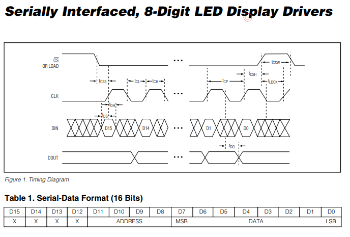
According to the above diagram, In order to write data to max7219, we need to do the following:-
1.) Pull the CS pin LOW
2.) Pull the clock pin LOW
3.) Write one bit to the data pin
4.) Pull the clock pin HIGH
5.) Repeat steps 2,3 and 4 until both address and data bytes are written
6.) Pull the CS pin HIGH
1.) Pull the CS pin LOW
2.) Pull the clock pin LOW
3.) Write one bit to the data pin
4.) Pull the clock pin HIGH
5.) Repeat steps 2,3 and 4 until both address and data bytes are written
6.) Pull the CS pin HIGH
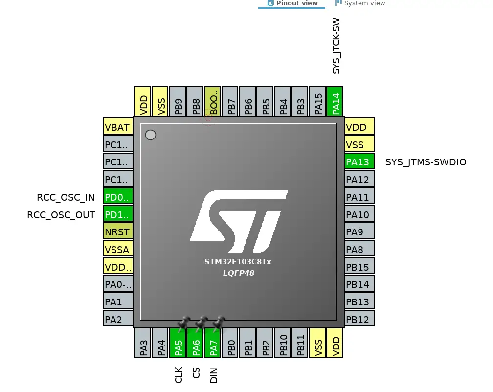
Also note that the data should be written in MSB first format. Let’s write the code for STM32 now. My CubeMx configuration is shown below..
Some Insight into the CODE
The following is the function for writing a byte to max7219
As you can see above that for writing each bit of data, we have to Pull the CLK pin low and than pull it high after writing the bit. Also byte&0x80 means that we are writing the MSB bit and than shifting the bit to left by using byte<<1.
Next we need to write another function for writing address and data to the MAX.
Next we need to write another function for writing address and data to the MAX.
Here we have to pull the CS pin LOW and after writing both address and data, pull it back to HIGH.

TO initialise the DOT matrix display we have to do the following:-
–> Set noo decode in the Decode mode register (0x09)
–> Set intensity value in the intensity register (0x0A)
–> Scan limit = 8 LEDs in 0x0b
–> value of 1 in the 0x0c denotes the normal power on mode
–> Set 0 in the Display test register (0x0f)
–> Set noo decode in the Decode mode register (0x09)
–> Set intensity value in the intensity register (0x0A)
–> Scan limit = 8 LEDs in 0x0b
–> value of 1 in the 0x0c denotes the normal power on mode
–> Set 0 in the Display test register (0x0f)
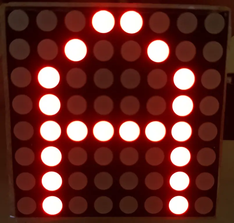
Now in order to display any character (For eg ‘A’), Think of the Registers from 0x01 to 0x08 as the addresses of the 8 ROWs and we need to turn the respective LEDs ON in each ROW. The following are the values for each row to display ‘A’
{0x18,0x24,0x42,0x42,0x7E,0x42,0x42,0x42}
You can check the code for more details.
{0x18,0x24,0x42,0x42,0x7E,0x42,0x42,0x42}
You can check the code for more details.

No comments:
Post a Comment