Tuesday, June 11, 2019

How to create 1 microsecond delay in STM32

HAL_Delay is able to provide minimum 1ms delay but when it comes to microsecond, there isn’t any predefined function to create 1us delay. In this tutorial, I am going to show you how to create 1 microsecond delay in STM32. The process will be same for all the STM32 devices, you need to make a minor change though.

WHY Delay in MicroSeconds

Delay in microseconds is needed in order to interface some sensors for eg- DHT11/22. These sensors contains only one PIN for the data transfer and data is transferred bidirectionally. They need precise timing in order to work. For eg- To initialize DHT22, microcontroller need to pull the data pin low for 500us and than pull high for 40us. After that DHT22 start transmitting it’s response by pulling the line low for 80us followed by pulling high for 80us.
After searching a lot on the internet, finally I got the code which works. I don’t remember where I got it from so if someone knows the writer, do let me know in the comments below. I will give the credits for the work.
I will show the working on the oscilloscope, You can check the  RESULTS tab for more details. I am using STM32F103C8 cortex M3 microcontroller but the process is same for other STM32 devices.

How to setup

This project contains a header file (dwt_stm32_delay.h) and a c file (dwt_stm32_delay.c). We need to include it in the main project. I am using keil and the process is described below:
First setup the project from the CubeMx and right click the Application/Userand select add existing files to group
add both files in the project
As you can see above that the folder is included in the path
Next you have to include dwt_stm32_delay.h in the main file by using #include “dwt_stm32_delay.h” and build the project. Now you will be able to see the *.h and *.c file in the list.
NOTE:-  Inside dwt_stm32_delay.h, change the #include”*.h” file according to your microcontroller.
You can use DWT_Delay_Init (); to initialize the delay and DWT_Delay_us (microseconds) for the delay in us.

#include <stdint.h>
#ifndef INC_DWT_DELAY_H_
#define INC_DWT_DELAY_H_
#define DWT_DELAY_NEWBIE 0
void DWT_Init(void);
void DWT_Delay(uint32_t us);
#endif /* INC_DWT_DELAY_DWT_DELAY_H_ */


#include "stm32f1xx_hal.h"          // change to whatever MCU you use
#include "dwt_delay.h"

/**
 * Initialization routine.
 * You might need to enable access to DWT registers on Cortex-M7
 *   DWT->LAR = 0xC5ACCE55
 */
void DWT_Init(void)
{
    if (!(CoreDebug->DEMCR & CoreDebug_DEMCR_TRCENA_Msk)) {
        CoreDebug->DEMCR |= CoreDebug_DEMCR_TRCENA_Msk;
        DWT->CYCCNT = 0;
        DWT->CTRL |= DWT_CTRL_CYCCNTENA_Msk;
    }
}

#if DWT_DELAY_NEWBIE
/**
 * If you are a newbie and see magic in DWT_Delay, consider this more
 * illustrative function, where you explicitly determine a counter
 * value when delay should stop while keeping things in bounds of uint32.
*/
void DWT_Delay(uint32_t us) // microseconds
{
    uint32_t startTick  = DWT->CYCCNT,
             targetTick = DWT->CYCCNT + us * (SystemCoreClock/1000000);

    // Must check if target tick is out of bounds and overflowed
    if (targetTick > startTick) {
        // Not overflowed
        while (DWT->CYCCNT < targetTick);
    } else {
        // Overflowed
        while (DWT->CYCCNT > startTick || DWT->CYCCNT < targetTick);
    }
}
#else
/**
 * Delay routine itself.
 * Time is in microseconds (1/1000000th of a second), not to be
 * confused with millisecond (1/1000th).
 *
 * No need to check an overflow. Let it just tick :)
 *
 * @param uint32_t us  Number of microseconds to delay for
 */
void DWT_Delay(uint32_t us) // microseconds
{
    uint32_t startTick = DWT->CYCCNT,
             delayTicks = us * (SystemCoreClock/1000000);

    while (DWT->CYCCNT - startTick < delayTicks);
}

#endif

LM35 Temperature sensor with STM32

LM35 is an integrated-circuit temperature device with an output voltage linearly proportional to the centigrade temperature. As LM35 is not calibrated in Kelvin, user does not require to subtract large constant voltage from the output to obtain convenient centigrade scaling.

Features of LM35

  • Calibrate directly in celcius
  • 0.5°C Ensured Accuracy ( at 25°C)
  • Rated for full -55°C to 150°C Range
  • Suitable for Remote Applications
  • Operates from 4V to 30V
  • Less than 60μA current drain
  • Low Self-Heating, 0.08°C in Still Air
  • Non-Linearity Only ±¼°C Typical
  • Low-Impedance Output, 0.1 Ω for 1-mA Load

Applications

  • Power Supplies
  • Battery Management
  • HVAC
  • Appliances
[/vc_message]
Click HERE to download LM35 datasheet.
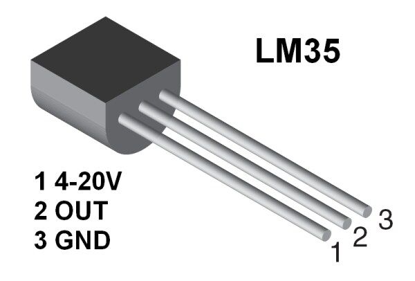
Connections in LM35
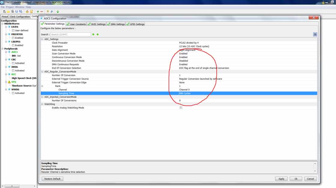
Go to ADC1 config in configuration tab and make sure your settings are as follows
Scan Conversion- Enabled Continuous conv- Enabled DMA request – Emabled Sampling time – Highest(480 cycles)
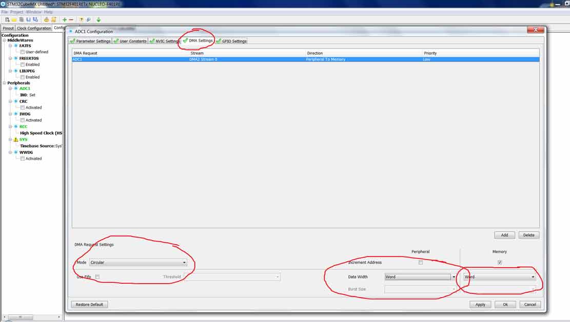
Go to DMA setting and select the following
That’s it for CubeMx setup. Generate the project and open it

Some Insight into the Code

create variables:-
uint32_t adc_buf is the ADC buffer, where values from LM35 will be stored.
int temp is the variable to store the temperature.
write a callback function:-

Measure input Frequency using STM32

In this tutorial today, I will show you guys How to measure input frequency using STM32. I know there are methods like input capture and compare etc.. but the method I am using is possibly the simplest and easiest to understand and can measure a very high range of frequencies.

HOW TO 

The process is pretty straight forward. We will set the data pin as input and count the number of times it goes high and low in 1 second and that will be the input frequency. I am using NE555 to generate different frequencies and DSO138 to compare the results to. 
The main problem is setting a 1 second interval for the measurement. For this purpose I will use TIMERx (x is your choice) and set the counter (CNT) as 0 and wait for it to reach max value(stored in ARR), which it will do in 1 second and within that time we will count the number of pulses.

SETTING UP THE TIMER

Okay this is the crucial part, so follow the steps below:-
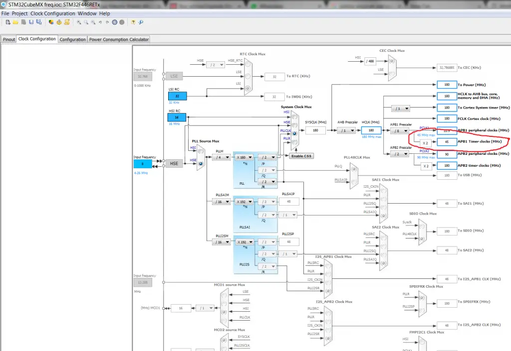
1.) Check that maximum frequency, your TIMx can operate on. For eg I am using TIM2 of STM32F446RE and according to the datasheet, it is connected to the APB1 bus.
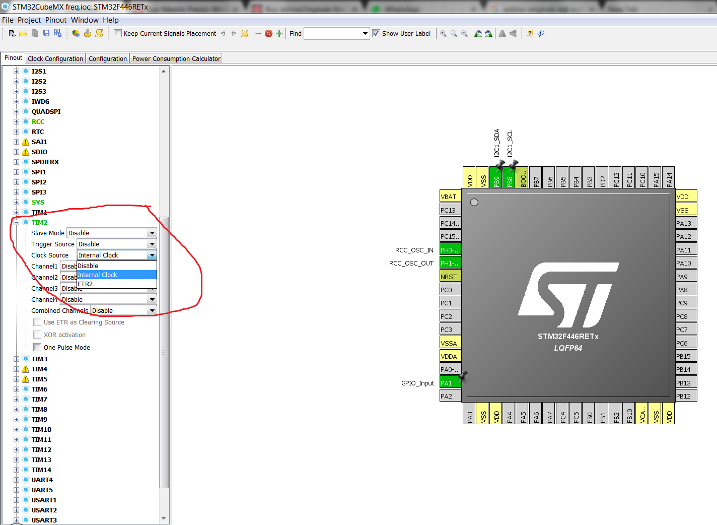
2.) Select the TIMx and choose clock source as internal clock.
3.) While setting up the clock, look at the APBx TIM clock. Also make sure this value is below 65000 to make the calculations more simpler.
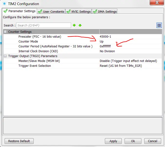
4.) Now my TIM2 is running at 45 MHz. So I will set my prescaler value at 45000 and I will get a frequency of 1 KHz (1 ms time period) from this setup. Also set the value of ARR to maximum possible value. As my ARR is 32 bit so I will set it to 0xffffffff.
This setup will ensure that the Timer will count from 0 to 0xffffffff in 1 ms and it will increment the count by 1 in the CNT register.

Insight into the CODE


HC-SR04 Ultrasonic sensor and STM32

Description

Ultrasonic ranging module HC – SR04 provides 2cm – 400cm non-contact measurement function, the ranging accuracy can reach to 3mm. The modules includes ultrasonic transmitters, receiver and control circuit. 
Today in this tutorial we are going to learn How to interface HC-SR04 Ultrasonic sensor module with STM32.

WORKING

Working of hcsr04 is pretty simple and straight. 
The module emits an ultrasound at 40 KHz which, after reflecting from obstacle, bounces back to the module. By using the travel time and the speed of the sound, we can calculate the distance between the sensor and the obstacle.

HOW TO

According to the datasheet of hc-sr04, the following is required to be done :-
  • Keep the pin HIGH for at least 10us
  • The Module will now send 8 cycle burst of ultrasound at 40 kHz and detect whether there is a pulse signal back
  • IF the signal returns, module will output a HIGH PULSE whose width will be proportional to the range of the object.
  • Distance can be calculated by using the following formula :- range = high level time * velocity (340m/s) / 2
  • We can also use uS / 58 = Distance in cm or uS / 148 = distance in inch 
  • It is recommended to wait for at least 60ms before starting the operation again.
Timing diagram of HC-SR04

Connection


CODE


Back to Top